Building Statistics Part 1
Building Statistics
General Building Data:
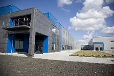
Building name: West Plant expansion
Location: Abu Dhabi, PA
Building Occupant Name: Fuala Factory
Occupancy Type: S-1, F-1, B, A-2, A-3
Size: Existing – 208,237 SF, Addition – 350,545SF
Number of stories: 3 total, 1 basement and 2 above grade.
Construction Dates: Sept 2010 – March 2012
Deliver Method: Design-Build with Guaranteed Maximum Price
Cost: GMP = Withheld by Owner
Primary project team:
Owner: Fuala Chocolates
General Contractor: Turner www.turnerconstruction.com
Architecture and Engineering: Nutec Group http://www.ntda.com/main/
Civil Engineer: Evans engineering http://www.evanseng.com/
Project Architecture:
The New West Plant is a factory of three floors as follows: A basement for production, storage and delivery; First floor for offices, storage, manufacturing and production; Second floor for production, office use and a fitness center. The floors are also separated into 15 sections, from A – J, each having a specific function in the new plant where areas K-O would be the old plant.
It is basically broken down into 3 sections; Left, center, right. Right is the old factory which currently running at 24 hours a day, 7 days a week. The center and left part are the new west expansions and they are as follows: The First floor includes both center and left extensions; mezzanine would only include the center section; and the basement would include the lower part of both new sections which is ¼ the actual size.
As mentioned, the Basement is only one fourth the size of the first floor and it contains the main production processes that take place in the plant that includes but is not limited to a syrup silo, chocolate silo and almond processing, distribution and storage. In addition to the rail shed, basement mezzanine and block dock.
On the First Floor is divided as such: Areas A, B, C, D and F are for packaging; Areas G and E are for syrup storage and manufacturing; Area H consists of mainly Fabrication and manufacturing lines in addition to a syrup lab, office and BU; I would be for the Mechanical and Electrical rooms.
The Second floor would hold business occupancy in Area B; A production mezzanine from Areas B, D, F and H; and a Fitness center in Area O.
Historic Requirements:
None
Codes:
International Building Code 2006
International Existing Building Code 2006
International Fire code 2006
International Mechanical Code 2006
International Code Council Electrical Code 2006
National Electrical Code 2005
International Energy Conservation Code 2006
Safety Code for Elevators and Escalators (ASTME A17, 1-2004)
ICC-ANSI 117.1-03 Accessible and usable Building and Facilities
Zoning:
The Fuala Plant is within the Zoning district of Abu Dhabi, PA. |
||||||||
|
Building Enclosure:
The basement enclosure is cast-in-place S.O.G. and exterior walls while a few of the interior walls are CMU walls or metal panel. The roof would be a precast concrete T beams as a roof with cast-in-place concrete which would be the first floor. The first floor would mainly consist of precast exterior walls with precast column while the roof of the plant would be an EPDM with insulation. However, the mezzanine would be steel columns with steel deck on U beams.
Sustainability Features:
Initially Turner pursued a LEED certification; however, after studying the factory’s process energy consumption, which turned out to be very large, Turner stopped pursuing a certification. Even though are not able to achieve a LEED certification since the process energy consumption was too high, many points were still achieved to accumulate a large number of 43 points with a potential to reach 52 points. A list of the sustainable features:
- Alternate transportation by providing parking spots and racks for Bicycle and Low-Emitting % Fuel efficient Vehicles
- Storm water design – quality control
- Water efficient Landscaping
- Water Use reduction
- Construction waste management up to 70% achievable
- Recycled content – up to 20% for high quantity of steel
- Indoor environmental quality : Outdoor air delivery monitoring, Indoor air quality management plan, low-emitting materials
- Innovation in Design: Regional Materials up to 30%, certified wood 95%, Maximize open Space
Building Statistics Part 2
Construction:
West Fuala plant expansion is an $83 million extension of the original facility which is over a century years old. The expansion will cover an area of 324,403 SF. The whole process will has started on June 2010 and is planning be completed by the end of February 2012. It a fairly isolated site since there are no adjacent buildings or structures that would affect construction; and so, there are no special requirements with regard to the public. The only special requirements, which Turner must attend to, are with regard to the existing old facility where they must maintain operating plant access, employee entrances, roadways and so on. All that must be taken into account in planning all of the site improvements to minimize the impacts to daily operations.
Fuala holds a GMP contract with Turner, the General Contractor, that later became a cost plus fee as a result of the drastic changes in scope that occurred. Fuala also hold direct contracts with the Nutec Group which took the role of the Architect and Engineer.
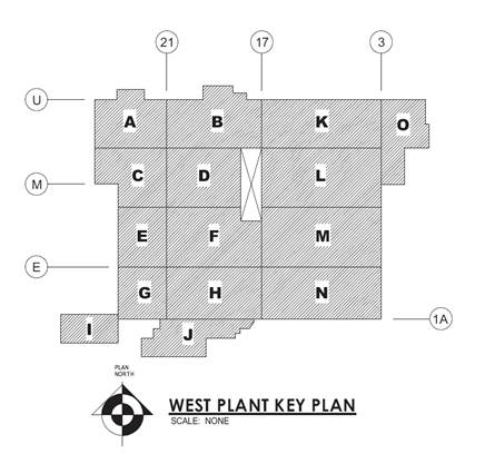
There will be 3 main phases when constructing this facility: Excavation and site work, superstructure and finally a Finishing phase. The sequence of construction will be basically east to west (17 – 23) and from South to north (A - J). Areas K – O to the east are part of the old facility. Areas G, H & I are the only areas with a basement.
Structural:
The overall structural building plan is as follows: A Cast-in-Place Concrete foundation for the entire building in addition to the basement, a precast shell which includes the wall, floor, columns and roof of the main structure, and finally a Steel mezzanine structure.
The Foundations would be made from cast-in-place along with the 8” concrete slab on grade reinforced with #5 @ 18” o.c.. The rest of the building shell would mostly consist if precast structures. There will be 24 x 24 precast columns all over the building expansion while the roof would consists of precast double Tees members; 32’ span for the basement and 64’ span for first floor. The precast walls would have a max width of 12’ with around a total of 210 precast wall units used for the entire structure. The Steel use in the building would be Wide Flange beams for the some framing areas while Hollow Steel Structure beams would be used for the mezzanine.
Electrical:
A new utility building will be created along with the new west plant expansion. This utility will have a new 69KV feeder along with the original 69KV feeder; this will generate a total of 1200 Amps (600 from each) that will feed into the plant from PPL. The 2 service entrances will be feeding 4 substations through distribution panels running a 3phase (4-wire) 277/480V circuit. In addition, each substation will have 2 backup generators running at 450KW – 562.5KVA.
As for the lighting systems, the entire building will have florescent lighting all over. They are all consistent and are uniform throughout the plant from the basement and up to the mezzanine. The fixtures will be T8 lamps and electronic ballasts. In addition, there are 2 back generators at each of the 4 substations that will activate upon loss of power.
Mechanical:
The mechanical system is placed in the southwestern part of the building (Area I) in the basement level of the west plant on a raised concrete pad. The overall HVAC system will feature a total of 32 VAV reheat units serving the entire west plant providing air at 180F. The reheat system ranges from 150 CFM up to 2400 CFM. The Cooling systems will be placed on the roof and will supply air at 42 F. There are 13 air handling units placed on the roof and 2 air handling exchangers.
Fire Protection:
There are 10 different fire protection systems throughout the west expansion. The main systems for the 10 risers has a dry pipe alarm valve connected to 8” Diameter fire pipes and 12” diameter pipe sleeve. This is then connected to an electric alarm bell on the outside wall. The fire protection code being followed for this project is NFPA 13.
Transportation:
The Building has consists of a basement and a first floor. And since the expansion is a plant there are only 2 elevators, located in areas G and H, which would be mainly used between the basement and the first floor in those areas. The elevators do not service the mezzanine area.
Links
User note:
-
While great efforts have been taken to provide accurate and complete information on the pages of cpep, please be aware that the information contained herewith is considered a work-in-progress for this thesis project. modifications and changes related to the original building designs and construction methodologies for this senior thesis project are solely the
interpretation of britnei godusky. changes and discrepancies in no way imply that the original designed contained errors or was flawed. differing assumptions, code references, requirements, and methodologies have been incorporated into this thesis project; therefore, investigation results may vary from the original design.